Mold Flipper: How to Plan Integration with Existing Cranes in Indonesia?
Are you running a busy workshop in Indonesia, constantly dealing with large, heavy molds? You probably know the challenge. Flipping these molds is a necessary evil. Doing it with chains and your overhead crane is slow, dangerous, and puts your expensive molds at risk. Every time you see a mold swing precariously, you worry about your team's safety and the potential for a catastrophic accident that could halt production for days. You need a better way, a solution that brings safety, efficiency, and peace of mind to your operations. A dedicated mold flipper is the answer, but the thought of integrating a new piece of heavy machinery into your existing setup can be daunting.
To successfully integrate a mold flipper with your existing cranes in Indonesia, you must begin with a comprehensive audit of your crane's capabilities, including its load capacity, hook height, and operational range. Next, you need to strategically plan the flipper's physical location and foundation to ensure structural integrity and seamless workflow. Finally, you must create a robust electrical and control system interface, complete with safety interlocks, to ensure the crane and flipper work together as a single, safe, and efficient unit.

I understand the hesitation. As an engineer who has spent my entire career in and around packing and handling machinery, I’ve seen what happens when integration is an afterthought. A powerful new machine can become a bottleneck if it doesn’t work perfectly with what you already have. But I've also seen how proper planning turns a simple equipment purchase into a massive upgrade for an entire production line. It's not just about adding a machine; it's about optimizing your whole process. Let's walk through the essential questions you need to ask to ensure your integration project in Indonesia is a complete success.
What key crane specifications must be checked before integration?
You have a powerful overhead crane in your facility, one that has served you well for years. It seems logical to assume it can handle placing a mold onto a flipper. But this assumption can be a costly mistake. An overhead crane's nameplate capacity might not tell the whole story, especially when introducing new dynamic movements and precise positioning tasks. Overlooking a single detail—like the true braking capacity or the slight wear in a lifting cable—could lead to equipment damage, or worse, a serious accident. The only way to proceed with confidence is to treat your existing crane as a critical variable that needs a thorough and honest evaluation.
Before integrating a mold flipper, you must meticulously verify your crane's rated lifting capacity, maximum hook height, lifting and travel speeds, and the full extent of its trolley and bridge travel range. It is crucial to confirm that the crane can not only handle the static weight of the mold but also the dynamic forces involved in lifting and placing it. You must also ensure there is sufficient vertical clearance and horizontal reach to access the flipper's loading and unloading zones without any obstruction.
Diving Deeper into Crane Assessment
A proper assessment goes far beyond just reading the numbers on the side of the crane. It requires a practical, hands-on approach. When I work with clients, we break this down into two main areas: the crane's physical limits and its operational space.
Analyzing Crane Capacity and Condition
The rated capacity is a starting point, not the final word. In a place like Indonesia, where a crane might be over 15 years old and operated in a humid environment, you have to consider its current condition.
- Age and Service History: Has the crane been regularly maintained? Are there detailed service logs? Older cranes, especially those without a clear history, should be professionally inspected and possibly derated for safety.
- Dynamic vs. Static Load: The crane's listed capacity is for a direct, vertical lift (static load). Placing a heavy mold onto a flipper requires precise, slow movements and braking, which introduces dynamic forces. You must ensure the crane's motors and brakes can handle these nuanced operations without strain.
- Component Wear: We always advise a close inspection of critical components. This includes the wire rope, hook, braking system, and trolley wheels. Any signs of significant wear or corrosion are red flags that must be addressed before the project continues.
Here is a simple checklist we use as a starting point. This should be completed with a qualified crane technician.
| Crane Specification | Key Requirement for Flipper Integration | Verification Method |
|---|---|---|
| Rated Capacity (SWL) | Must exceed the combined weight of the heaviest mold + lifting gear (chains, slings, etc.) by a safe margin (e.g., 25%). | Review crane documentation and conduct a load test if necessary. |
| Hook Height | Must be high enough to lift the mold clear of the flipper and any surrounding obstacles. Formula: Mold Height + Flipper Height + Rigging Height + Safety Clearance < Max Hook Height. |
Physical measurement from the floor to the fully raised hook. |
| Travel Speeds | Must have slow/variable speed control for precise placement. High-speed-only cranes are a risk for this task. | Test the crane's variable speed controls (if available) with a load. |
| Brake Integrity | Brakes must be able to hold the load steady during the delicate positioning phase without any drift. | Perform a brake holding test with a representative load. |
Mapping the Operational Envelope
The "operational envelope" is the three-dimensional space where the crane can safely operate. You need to ensure the mold flipper is placed squarely within this envelope. I recall a client who almost installed their new flipper in a corner of their bay, only to realize during our pre-installation check that a large structural column created a blind spot for the crane's trolley. A simple mapping exercise prevented a costly relocation. You must map out the crane's full travel path, noting any no-go zones created by columns, cable trays, or other machinery. This ensures the operator has a clear line of sight and the crane has unobstructed access to place the mold perfectly on the flipper's table every single time.
How do you ensure structural and foundation safety for the new mold flipper?
You've found the ideal location for your new mold flipper. It's close to your presses, the area is clear, and it seems like a perfect fit for your workflow. The concrete floor looks thick and solid. But that concrete was likely poured with a simple purpose in mind: to support the static weight of equipment or stored materials. A mold flipper is different. It concentrates immense and shifting forces onto a small footprint. A 50-ton mold being tilted from vertical to horizontal exerts a powerful dynamic load that the ground beneath it was never designed to handle. Ignoring this could lead to cracks in the foundation, machine misalignment, and eventually, a catastrophic failure that jeopardizes both your investment and your team.
To guarantee structural and foundation safety, you must first obtain the mold flipper's technical specifications, which detail its dead weight and, more importantly, the dynamic loads it exerts during the tilting cycle. With this data, you must commission a local civil engineering firm in Indonesia to conduct a geotechnical assessment of the proposed installation site. This involves analyzing the concrete slab and the sub-soil's load-bearing capacity to determine if the existing foundation is adequate or requires reinforcement.
Diving Deeper into Foundation Integrity
The foundation is the literal base of your entire operation's safety and reliability. In my experience, this is the one area where you should never try to save money. The cost of a proper analysis is a tiny fraction of the cost of failure.
Understanding the Forces at Play
A mold flipper doesn't just sit there; it performs a powerful mechanical action. Thinking about these forces is key.
- Static Load: This is the machine's own weight plus the weight of the mold when it's at rest. It's a significant number, but it's predictable.
- Dynamic Load: This is the crucial factor. As the flipper tilts the mold, the center of gravity shifts. This creates a powerful torque and transfers constantly changing stress to the anchor points and the foundation below. This force can be much greater than the static load and is what can cause concrete to fracture over time.
- Vibrations: The hydraulic or electromechanical systems also generate vibrations during operation. Over thousands of cycles, these vibrations can contribute to the degradation of a poorly prepared foundation.
In industrial areas across Indonesia, factors like high humidity and varying soil conditions can also impact the long-term stability of concrete. A foundation that appears fine on the surface may have underlying issues.
Practical Steps for Foundation Verification and Preparation
A systematic approach ensures nothing is missed. When a client partners with us at SHJLPACK, we guide them through this process.
- Data Collection: We provide the client with detailed drawings of the mold flipper, including the exact location of the anchor points and the precise static and dynamic load calculations for their specific model.
- Hiring Local Expertise: We always insist the client hires a reputable, local civil engineering consultant. They will understand the local building codes, soil conditions, and construction practices in Indonesia.
- On-Site Assessment: The engineer will typically perform tests. This might include a visual inspection, using a Schmidt hammer for concrete hardness, or taking core samples to analyze the thickness and composition of the slab and the sub-base.
- Engineering Report: The consultant provides a formal report. This will state clearly whether the existing foundation is sufficient or if remediation is needed.
- Reinforcement (If Needed): If the foundation is inadequate, the report will specify the solution. This could involve cutting out the existing slab, digging deeper, creating a new sub-base, and pouring a new, reinforced concrete foundation with a steel rebar cage designed to handle the specific loads of the flipper.
This process is your insurance policy. I once worked with a factory manager who was hesitant to spend on the engineering report. We convinced him it was necessary. The report found that the concrete slab was half as thick as he believed. The small investment in a new foundation pad saved him from what would have been a six-figure repair and months of downtime.
| Foundation Safety Step | Key Consideration | Responsible Party |
|---|---|---|
| 1. Obtain Machine Specs | Get load data, anchor patterns, and dynamic force calculations. | Machine Supplier (e.g., SHJLPACK) |
| 2. Hire Civil Engineer | Select a certified engineer with industrial foundation experience. | Client (Factory Owner) |
| 3. Conduct Site Survey | Analyze concrete thickness, rebar presence, and soil bearing capacity. | Civil Engineer |
| 4. Review Engineer's Report | Get a clear "go" or "no-go" with specific recommendations. | Client & Engineer |
| 5. Execute Foundation Work | Prepare the site exactly as specified in the engineering drawings. | Client / Hired Contractor |
What are the critical steps for electrical and control system integration?
The mold flipper is bolted to the floor, and the crane can reach it perfectly. The mechanical work is done. But now comes the most critical part for operational safety: making the machines talk to each other. If the crane operator can start lifting while the mold is still clamped by the flipper, you have a recipe for disaster. If the control systems are separate and confusing, your operators will be inefficient and prone to making mistakes under pressure. A truly successful integration is achieved when the electrical and control systems turn two separate machines into one cohesive, intelligent unit.
The critical steps for electrical and control system integration begin with ensuring your facility's power supply in Indonesia (voltage, phase, frequency) matches the mold flipper's requirements, and installing correctly sized cabling and circuit protection. For the control system, you must implement safety interlocks—using sensors and relays—that physically prevent the crane from operating while the flipper is in motion, and vice versa. This creates a fail-safe system that protects your people and equipment.

Diving Deeper into System Integration
This is where my background as a hands-on engineer becomes so important. I've seen firsthand how a well-thought-out control system can transform an operation, making it faster, safer, and less reliant on operator skill alone.
Matching Power and Building a Robust Electrical Foundation
Before a single wire is connected, you need to confirm the basics. In Indonesia, the standard industrial power supply is typically 380V, 3-phase, 50Hz, but you must never assume.
- Verify Power Supply: Use a multimeter to check the actual voltage at the connection point. The power quality in some industrial zones can fluctuate, so you might also consider if a power conditioner or surge protector is needed to protect the flipper's sensitive electronics.
- Dedicated Circuit: The mold flipper should have its own dedicated circuit with an appropriately rated circuit breaker. Sharing a circuit with other heavy machinery can lead to voltage drops and nuisance tripping.
- Correct Cabling: Use cables that are properly sized for the motor's amperage draw and the distance from the main panel. Undersized cables can overheat, which is a serious fire hazard. Ensure all wiring is done by a qualified electrician who follows local Indonesian safety standards (PUIL - Persyaratan Umum Instalasi Listrik).
The Core of Safety: Interlocks and Control Logic
This is the "brain" of the integrated system. Interlocks are not just suggestions; they are physical or electrical stops that prevent unsafe actions.
- What are Interlocks? They are simple cause-and-effect rules enforced by the machinery. For example, a limit switch on the flipper's clamp sends a signal. If the clamp is closed, it physically breaks the circuit that allows the crane's hoist motor to activate. The operator can press the "lift" button all day, but nothing will happen until the flipper confirms the mold is unclamped and free.
- Types of Sensors: We use a combination of sensors to create a robust safety net. Proximity sensors can detect if the mold is seated correctly on the flipper table. Limit switches confirm when the flipper has completed its 90-degree rotation.
- Control Panel Design: The goal is to make the safe choice the easy choice. Instead of having two separate pendants or control panels, we often recommend a unified control station. This panel can have a simple selector switch: "Crane Mode" or "Flipper Mode". Or even better, a semi-automated sequence. The operator presses one button to "Start Flip Cycle," and the system automatically checks all safety conditions before executing the flip.
Here is an example of the logic we would program into the control system:
| Condition | Crane Hoist Action | Flipper Tilt Action | System Status Light |
|---|---|---|---|
| Mold is clamped & Flipper is not at 0°/90° | DISABLED | ENABLED | Yellow (In Cycle) |
| Flipper is at 0° or 90° & Mold is unclamped | ENABLED | DISABLED | Green (Ready for Crane) |
| Mold is NOT detected on table | ENABLED | DISABLED | Blue (Awaiting Mold) |
| Emergency Stop is pressed | DISABLED | DISABLED | Red (Fault) |
This level of integration directly addresses goals like improving safety and pushing towards digitalization. It reduces human error and creates a predictable, repeatable, and highly efficient process.
How can you create a safe and efficient workflow between the crane and the flipper?
You’ve done everything right. The crane has been certified, the foundation is solid, and the electrical interlocks are working perfectly. Yet, when you watch the operation, it feels clunky and slow. The crane operator waits for the ground crew, who are unsure where to stand. Time is wasted during handovers. The new system isn't delivering the efficiency gains you expected. This happens when the focus is only on the hardware. The most sophisticated equipment is only as effective as the human process built around it. A well-designed workflow is the final, essential piece that unlocks the full potential of your investment.
To create a safe and efficient workflow, you must start by clearly mapping out every step of the operational sequence, from the initial mold pickup to its final placement after being flipped. Use this map to design the physical layout, painting clear operational zones on the floor for the machinery and safe zones for personnel. Finally, document this entire process in a clear Standard Operating Procedure (SOP) and use it to conduct hands-on training for all operators and ground staff.
Diving Deeper into Operational Excellence
As someone who ran a factory before focusing on SHJLPACK, I learned that smooth processes are where you find hidden profits. A good workflow eliminates wasted motion, reduces the chance of errors, and creates a less stressful environment for your team.
Designing the Physical and Operational Flow
The goal is to make the process as logical and linear as possible, like a well-organized assembly line.
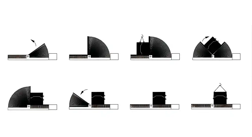
- Map the Sequence: Write down every single step. For example:
- Crane picks mold from storage rack A.
- Crane travels to the flipper zone.
- Ground staff confirms the flipper is ready.
- Crane operator slowly lowers the mold onto the flipper table.
- Ground staff checks for correct seating and gives a "clear" signal.
- Crane detaches rigging and moves to a pre-defined "safe standby" position.
- Flipper operator executes the 90-degree flip.
- Crane moves back into position to re-engage with the flipped mold.
- Crane lifts the mold and transports it to press machine B.
- Visual Management on the Floor: This is incredibly effective. Use industrial floor paint to create clear visual cues:
- A yellow hatched box around the mold flipper indicating a "machine operational area - no entry."
- A green box where the operator should stand to use the controls.
- A blue box painted on the floor marking the "crane safe standby" position.
- Clear walkways for personnel that do not cross the crane's primary path.
This simple act of painting lines on the floor removes ambiguity and improves safety overnight.
The Human Factor: Training and Clear Communication
Your people are your most valuable asset. Investing in their training ensures they can use the new system confidently and safely.
- Develop a Standard Operating Procedure (SOP): This should be a simple, clear document, ideally with pictures or diagrams. It should not be a complex engineering manual. It should be a step-by-step guide for the operator. If your workforce in Indonesia primarily speaks Bahasa Indonesia, the SOP must be written in their language.
- Hands-On Training: Classroom training is not enough. You must conduct hands-on training sessions with the actual equipment. Walk through the SOP step-by-step. Let the operators practice the movements with a test mold.
- Clear Communication Signals: Establish a simple, non-verbal communication system. This could be a standardized set of hand signals or a simple light tower (red/yellow/green) that indicates the system's status. This is crucial in a noisy factory environment where verbal commands can be misheard.
This table shows how you can break down the SOP for clarity:
| SOP Step | Operator Action | Key Safety Check | Communication Signal |
|---|---|---|---|
| 1. Load Mold | Crane Operator lowers mold. | Ground staff visually confirms mold is centered on the flipper table. | Ground staff gives "thumbs up" to Crane Operator. |
| 2. Secure Mold | Flipper Operator presses "Clamp". | Flipper Operator confirms "Clamped" indicator light is on. | N/A |
| 3. Flip Mold | Flipper Operator presses "Flip". | All personnel are outside the yellow hatched safety zone. | A flashing yellow light activates during the flip cycle. |
| 4. Release Mold | Flipper Operator presses "Unclamp". | Flipper Operator confirms "Unclamped" indicator light is on. | Flipper Operator gives "thumbs up" to Crane Operator. |
A well-defined workflow like this directly supports goals like increasing equipment uptime to 95%. When every step is planned, there is no hesitation, no waiting, and a dramatic reduction in the risk of accidents that cause downtime.
Conclusion
Successfully integrating a mold flipper is a systematic process. It requires careful planning that addresses your crane's capabilities, the foundation's strength, control system safety, and your team's workflow.
My Insight
When I transitioned from being an engineer in a factory to starting my own, the biggest lesson I learned was this: a machine is never just a machine. It's a component in a much larger system that includes your people, your processes, and your physical space. Buying a mold flipper isn't the solution. Integrating a mold flipper is the solution.
Thinking about the crane, the foundation, and the workflow isn't an extra cost or a hassle. It is the core of the project. It's how you turn a piece of steel and motors into a genuine asset that makes your business safer, faster, and more profitable. As your partner, my focus isn't just to sell you a machine from my catalog. My goal is to understand your entire operation and ensure that what we provide helps your entire system improve. We succeed when you succeed. To me, that is the true meaning of a "TOTAL SOLUTION".


