Upender Machine Installation: What Space, Power, and Anchoring Are Required?
Thinking about adding a new upender to your production line is a smart move. It can significantly improve material handling efficiency and safety. But the excitement of a new machine can quickly turn into a major headache if the installation isn't planned correctly. You might be worried about the project getting bogged down by unforeseen site requirements, leading to budget overruns and delays that halt your production. It's a valid concern; a poorly planned installation can mean your investment doesn't deliver the ROI you need and creates more problems than it solves. As an engineer who has overseen hundreds of these installations, I'm here to provide a clear, practical guide. I'll walk you through the essential requirements for space, power, and anchoring, so you can plan with the confidence of a seasoned pro and ensure your installation is a success from day one.
To install an upender machine, you must allocate sufficient floor space for the machine's footprint plus an operational envelope for tilting, ensure overhead clearance for the load, provide a dedicated electrical circuit rated for the motor's peak load, and prepare a reinforced concrete foundation of adequate thickness and strength to securely anchor the machine against dynamic forces.
These three core elements—space, power, and foundation—are the pillars of a successful upender installation. Getting any one of them wrong can compromise the entire project. But when you understand the "why" behind each requirement, you can work with your team to prepare the site effectively. This isn't just about following a manual; it's about setting your equipment up for a long life of reliable, safe, and efficient operation. Let's break down each of these critical areas so you know exactly what to expect and how to prepare.
What is the ideal footprint and clearance for a heavy-duty upender?
You've identified a spot on the factory floor that looks big enough for your new upender. But simply measuring the machine's base dimensions and taping out a square is a common and costly mistake. The real-world space requirements go far beyond the machine's static footprint. If you fail to account for the full range of motion, operator access, and maintenance needs, you create an unsafe and inefficient work cell. This can lead to operators working in dangerously tight quarters, maintenance tasks being skipped because they are too difficult to perform, and potential collisions that damage the machine, the product, or surrounding infrastructure.
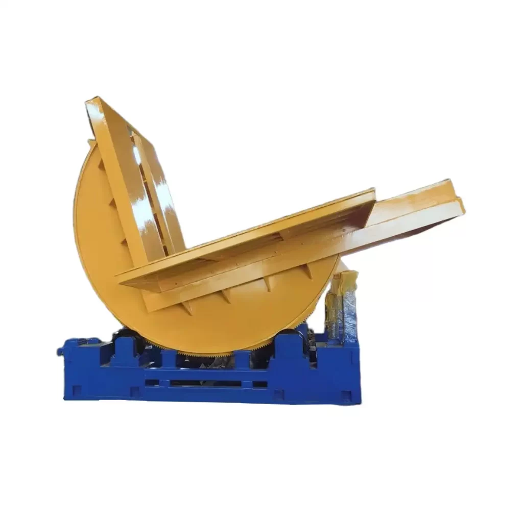
For a heavy-duty upender, the ideal space includes the machine's physical footprint, an operational envelope that fully accommodates the 90-degree tilting motion of your largest coil, and a safety clearance of at least 1.5 meters (5 feet) on all sides for operator movement and maintenance access.
%[A 90-degree coil tilter showing its range of motion.](https://www.fhopepack.com/blog/wp-content/uploads/2023/07/Coil-Tilter-Upender133-768x641.webp "Coil Tilter Space Clearance")
Deconstructing the Required Space
To plan effectively, you need to think about your space in three distinct zones. Each zone serves a critical purpose, and underestimating any of them can lead to problems down the line. As a plant owner, thinking in these terms helps you visualize the final work cell and ensure it aligns with your production flow and safety standards.
- Machine Footprint: This is the most straightforward measurement. It is the length and width of the machine's base that will be anchored to the floor. You'll get this dimension directly from the manufacturer's technical drawings.
- Operational Envelope: This is the most critical and often misjudged area. It's the total three-dimensional space the machine and your load will occupy during a full 90-degree cycle. You must consider the machine's tilting platform height and add the maximum diameter or height of the coils or products you will be handling. This defines a large arc of movement that must be completely clear of any obstructions like columns, walls, or other machinery.
- Maintenance and Safety Zone: This is the buffer zone around the operational envelope. I always recommend a minimum of 1.5 meters. This space allows operators to move around the machine safely without entering the tilting zone. It provides forklift access for loading and unloading. Crucially, it gives your maintenance team the room they need to perform inspections, lubrication, and repairs safely and efficiently, which is key to achieving the kind of 95% uptime you're targeting.
A Real-World Example
I remember working with a steel service center in Monterrey. They were excited about their new 25-ton upender. Their team had laid out the position based on the machine's footprint, placing it snugly between a support column and their main slitting line to save space. During our pre-installation site review, we immediately flagged this. We took the coil's max diameter and physically mapped out the operational envelope. It became clear that during the tilt, the edge of the coil would come within inches of the support column. Furthermore, there was no room for a technician to access the hydraulic power unit for servicing. By catching this early, we were able to relocate the machine just five meters away. It seemed like a small change, but it prevented a guaranteed bottleneck and a major safety hazard. That simple check ensured their investment would enhance, not hinder, their workflow.
| Space Zone | Description | Recommended Minimum | Why It's Critical for a Steel Mill |
|---|---|---|---|
| Machine Footprint | The physical area the machine base occupies. | As per manufacturer's drawing (e.g., 3m x 4m). | The starting point for all other calculations. |
| Operational Envelope | The 3D space used during a full tilt cycle. | Footprint + Load Dimensions + Motion Arc. | Prevents collision with infrastructure or personnel. Ensures product isn't damaged. |
| Safety & Maint. Zone | A clear buffer around the operational area. | 1.5 - 2.0 meters on all sides. | Ensures operator safety, allows for forklift access, and enables preventative maintenance. |
| Material Staging | Area for queuing coils before/after tilting. | Depends on workflow (e.g., space for 2-3 coils). | Prevents bottlenecks and keeps the main production line fed smoothly. |
How do you calculate the power supply requirements for a hydraulic upender?
You've planned the space, and now it's time to think about power. It's tempting to assume that an existing power drop nearby will be sufficient. This is a dangerous assumption, especially in a steel mill where the electrical grid is already supporting heavy equipment. Under-provisioning power for your new upender is a recipe for operational disruption. At best, you'll deal with frequently tripped breakers. At worst, you can cause voltage drops that affect other sensitive equipment on the same circuit, and you risk damaging the upender's motor by starving it of the power it needs, especially during startup.
To accurately calculate the power supply needs, you must determine the motor's full-load amperage (FLA) based on its kilowatt (kW) rating and your site's operating voltage (e.g., 480V/3-Phase/60Hz). You then size the circuit breaker and wiring to handle the much higher inrush current during startup, typically adding a 25% safety margin to the FLA for continuous operation.
Key Factors in Power Calculation
Getting the power right is about more than just looking at the motor's nameplate. It involves understanding a few key electrical principles and how they apply in a demanding industrial environment like yours. A stable and correctly sized power supply is fundamental to the machine's reliability and connects directly to your goals of reducing energy costs and improving equipment uptime.
- Motor Power (kW or HP): This is the starting point. It tells you how much work the motor can do. For an upender, this is directly related to the machine's capacity and speed. A 30-ton upender will naturally require a more powerful motor than a 5-ton one.
- Voltage, Phase, and Frequency: This must match your plant's electrical system. For a steel mill in Mexico, this is typically 440V or 480V, 3-Phase, at 60Hz. Using the wrong voltage is a non-starter and can instantly destroy the motor.
- Full Load Amps (FLA): This is the amount of current the motor draws when operating at its rated full load. This is the number you use to size your wiring and overload protection.
- Starting Current (Inrush Current): When a motor starts, it briefly draws a current that can be 5 to 8 times higher than its FLA. Your circuit breaker must be sized to handle this momentary surge without tripping. This is why you can't simply use a breaker rated for the FLA.
Sample Calculation for a Steel Mill Upender
Let's imagine you are installing a 20-ton upender, which is a common size. It typically comes with a 7.5 kW motor. Here’s how we would approach the power calculation for your facility in Mexico, which uses a 480V/3-Phase/60Hz supply.
| Parameter | Value / Formula | Result & Notes for Your Team |
|---|---|---|
| Motor Power | 7.5 kW | A standard, efficient choice for this capacity. |
| System Voltage | 480V, 3-Phase, 60Hz | Confirm this with your plant's chief electrician. |
| Power Factor (cos φ) | ~0.85 (assumed) | This is a measure of electrical efficiency; it's on the motor's data sheet. |
| Motor Efficiency (η) | ~0.90 (assumed) | Modern motors are highly efficient, which supports your energy reduction goals. |
| Full Load Amps (FLA) | (kW * 1000) / (V * 1.732 * cos φ * η) |
(7500) / (480 * 1.732 * 0.85 * 0.90) ≈ **11.8 Amps** |
| Recommended Wire Size | Based on FLA and distance | For 11.8A, a 12 AWG wire is likely sufficient, but check local electrical codes. |
| Breaker Sizing | Rule of thumb: FLA x 2.5 | 11.8A * 2.5 = 29.5A. A 30A or 40A motor-rated breaker is appropriate. |
This calculation shows that you need a dedicated circuit capable of supplying at least 11.8A continuously, with a breaker that can handle the high inrush current. It’s why simply plugging it into any existing 3-phase outlet is not an option. A dedicated, properly sized circuit is non-negotiable for safety and reliability.
Why is proper foundation anchoring critical for an upender's safety and longevity?
After carefully planning the space and power, the final step before the machine arrives is preparing the foundation. It's easy to see this as simple construction work—just a slab of concrete with some bolts. But I cannot overstate this: the foundation is the most critical element for the safety and long-term health of your upender. The immense forces generated by tilting a multi-ton steel coil are all transferred directly into the floor. An inadequate foundation will fail under this stress. This won't happen overnight, but it will happen. You'll see increased vibration, followed by cracks in the concrete, and eventually, the machine itself could shift. This creates a catastrophic safety risk and will absolutely destroy the machine's precision and shorten its operational life.
Proper foundation anchoring is critical because it must safely absorb and dissipate the massive dynamic torque and vibration generated when tilting a heavy load. A correctly engineered, reinforced concrete foundation with high-strength chemical or expansion anchors prevents machine movement, ensures stability for precise operation, and is the ultimate safeguard for your personnel and equipment.
The Physics of a Tilting Load
Think about what happens when your upender lifts a 20-ton steel coil. As the platform tilts from horizontal to vertical, the center of gravity of that 20-ton mass shifts dramatically. This creates a powerful twisting force, or torque, on the base of the machine. At the same time, the hydraulic system and moving parts generate constant vibration. The anchor bolts and the concrete they are set in are the only things resisting these forces and keeping the machine locked in place. If the concrete is too thin or not strong enough, the anchors can pull out. If the anchors are of the wrong type or improperly installed, they can shear off. This is why we don't just "pour a pad"; we engineer a foundation.
A Cautionary Tale from the Field
I once consulted for a pipe mill that was having issues with its five-year-old upender. The machine was used to tilt bundles of steel pipe. They reported that it had become "unreliable" and was causing alignment issues with their downstream conveyor system. When I arrived, the problem was immediately obvious even before I turned the machine on. There were visible hairline cracks in the concrete radiating out from the base of the machine. We placed a dial indicator on the base and ran a cycle. The machine was physically shifting by several millimeters with every tilt. Their original installer had simply bolted the machine to the existing factory floor, which was only 150mm thick. It was never designed for such dynamic loads. The constant vibration and torque had fractured the concrete. My recommendation was tough but necessary: take the machine offline, break up the old floor, and pour a dedicated, 500mm thick reinforced concrete foundation. It was a costly repair, but it saved the machine and, more importantly, eliminated a serious safety risk. This is a perfect example of how skimping on the foundation leads to much higher costs later on, directly impacting your profitability and uptime goals.
| Foundation Feature | Inadequate Foundation | Properly Engineered Foundation | Consequence of Failure |
|---|---|---|---|
| Concrete Thickness | < 200mm (8 inches) | > 300mm (12 inches), often more | Cracking, instability, anchor pull-out. |
| Concrete Strength | Standard, unknown PSI | > 3000 PSI (C25/30), lab verified | Concrete crumbles under dynamic load. |
| Reinforcement | None or light mesh | Steel rebar grid (e.g., #5 rebar at 12" OC) | Lacks tensile strength to resist cracking. |
| Curing Time | < 14 days | Minimum 28 days for full strength | Anchors installed in "green" concrete will fail. |
| Anchor Type | Standard wedge anchors | High-strength chemical or heavy-duty expansion anchors | Anchors can shear, stretch, or pull out. |
Investing in a proper foundation isn't an option; it's a requirement for any business leader who, like you, prioritizes long-term stability and ROI over short-term savings.
You've received the quote for the upender machine itself, and the price fits your capital expenditure budget. The project is a green light. But the machine's price tag is only part of the total project cost. First-time buyers are often caught by surprise when the final bill for the installation comes in significantly higher than expected. These "hidden" costs, if not planned for, can damage your project's credibility and eat into the very ROI you worked so hard to calculate. As a former factory manager myself, I know the pressure you're under to control costs and deliver projects on budget. The last thing you need is to go back to your board or finance team asking for more money because of something that should have been anticipated.
Beyond the machine's purchase price, a plant manager must create a comprehensive budget that includes civil engineering for the foundation, licensed electrical work for the dedicated power line, rigging and crane services for placement, on-site commissioning and training by the supplier's technician, and the opportunity cost of production downtime during the installation period.
Budgeting Beyond the Price Tag
A successful project manager, and a successful CEO, looks at the total cost of ownership, not just the initial purchase price. The installation is a major part of that initial investment. By thinking through the entire process from delivery to handover, you can build a realistic and defensible budget. This foresight is what separates a smooth installation from a chaotic one. It demonstrates to your team and stakeholders that you are a forward-thinking leader who manages investments strategically. Let's break down the items that need to be on your budget checklist.
A Checklist for a Comprehensive Budget
I advise all my clients to use a checklist like this to avoid any surprises. It turns the "hidden" costs into line items you can plan for and manage. For a business leader like you, who has guided a company to a 2 million-ton capacity, this level of detail is second nature, but it's always good to have a framework.
| Cost Category | Description & Details | Estimated % of Machine Cost | Notes for a CEO like Javier |
|---|---|---|---|
| 1. Civil Works | Excavation, forming, rebar installation, concrete pouring, and finishing for the foundation. | 5-10% | Get a competitive quote from a trusted local contractor. This is a key area where quality cannot be compromised. |
| 2. Electrical Work | Running a new, dedicated power line from a panel to the machine. Includes conduit, wiring, a new breaker, and labor. | 3-7% | Your in-house electrical team can likely manage this, but budget for materials and man-hours. Crucial for power stability. |
| 3. Rigging & Lifting | Rental of a forklift or crane with sufficient capacity. Includes certified riggers to safely unload and position the machine. | 2-5% | This is a specialized skill. Using certified professionals is non-negotiable for safety and insurance purposes. |
| 4. Shipping & Logistics | Freight costs from the manufacturer to your plant, plus any customs clearance or brokerage fees. | Varies by location | Clarify if shipping is included (FOB vs. CIF). For Mexico, overland freight and customs are significant factors. |
| 5. Commissioning | The supplier's engineer on-site to supervise final assembly, connect power, test all functions, and calibrate the machine. | 2-4% | This is the mark of a strategic partner, not a box-shifter. This fee ensures the machine performs to spec from Day 1. |
| 6. Training | Formal training for your operators on safe operation and for your maintenance team on preventative maintenance schedules. | 1-2% | Essential for achieving your 95% uptime goal and reducing long-term repair costs. An investment in your people. |
| 7. Integration | If the upender needs to communicate with your MES or other automation (e.g., conveyors), budget for PLC programming and IT support. | 1-5% | Directly supports your goal of digital transformation and achieving full production visualization. |
| 8. Production Downtime | The opportunity cost of the production area being shut down during installation work. | Varies | The most "hidden" cost of all. Plan the installation during a scheduled plant shutdown to minimize this financial impact. |
By accounting for these items upfront, you present a complete and professional project plan. It shows you've considered all angles and are managing the company's capital with diligence and expertise.
Conclusion
Proper installation isn't an expense; it's an investment in safety, efficiency, and decades of reliable performance for your upender machine. Plan it right from the start.


